|
Parallel Port LCD Cheap & Easy
-- Page 2
Page 1
2
3
4
5
6
Before Wiring, THINK Where!!! Now that you got all your parts together, I know you can't wait to start
putting it together. But, the first thing your going to do is take the LCD out of the
package. Of coarse, I'm sure you all ready did that. Take a look at the
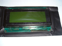
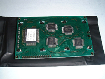
LCD and the controller board, and take a mental note of the size of it.


Ask yourself 'where the hell am I going to mount this damn thing?'. If
you got the same LCD as me you'll notice that the LCD screen by it's
self will fit in a single 5¼ Drive bay.

It will NOT fit with the controller board attached. So with that in mind
I was thinking of mounting it in the top bay. The problem with that was
I won't be able to use the second bay for a standard component, like a
CD drive. If I mounted it a middle day I would lose one on top and one
on the bottom. And in the bottom bay it would be to hard to see. Therefore
I ruled out using a drive bay. I decided to make my own hole. HEHE any
excuse to break out the DREMEL.
Alrighty then, I was getting to it. The wiring for this
thing is pretty simple. First you might be wondering what a
Potentiometer is or does. Also known as a Pot. Think of it as a volume
control, when you turn the control up it allows more voltage through,
and when you turn it down the pot allows less voltage. In this project
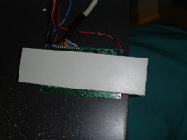
the pot is used to control the contrast and brightness of the LCD. This is how you connect it.

The center pin is usually the most important because it
is the control. The pins on the left and right go to the ground and power(usually).
Which way you want to turn the dial, clockwise or counterclockwise, to
adjust for hi and low depends on the side you connect power line to.


All Rights Reserved. 2001 Design by Disco.
| 
